Avi/NSX ALB - Virtual Service placement in A/A and N+M Elastic HA modes
One of the main challenges when we are designing and implementing Avi/NSX Advanced Load Balancer configurations will be the decision between which of the Elastic HA Mode to use and what are the differences between the two.
We are not covering the Legacy HA since normally do not represent a challenge being a well established topology.
Legacy HA for Avi Service Engines
Basic Concepts
Placement
- The Controller is the component responsible to decide where to place a Virtual Service
- Each Virtual Service has a property defining the minimum number of Service Engines for the VS to be placed
- The placement algorithm will be run multiple times by the Controller for each new/enabled VS until the minimum number of Service Engines configured for that VS is achieved
- In a Write Access cloud, the outcome of the placement algorithm could involve creation of new Service Engines and network “plumbing” changes to provide the necessary connectivity
- In case of a Service Engine failure, the affected VSs will be re-placed using the same algorithm
SE Group Parameters
There are some Service Engine Group parameters that also influence the VS placement:
- Max SEs per group
- Max number of SEs that can be provisioned in the SE Group. (Applicable only in Write-Access cloud)
- Max VS per SE (v)
- Max number of VSs than can be place in each individual SE
- Min scale per VS
- Number minimum of SEs that a VS will be placed
- Max scale per VS
- Number of maximum of SEs that a VS will be placed
- Buffer (b)
- Additional SE capacity that should be available for HA. This parameter determines the number of SE failures that we can handle in the SE group before we drop below our desired HA threshold, considering the Max VS per SE that we configured.
Some calculations
The Controller (SE Resource Manager ) takes care to calculate how much capacity is needed in each SE group.
The capacity required in each SE group is calculated based in the number of VSs and their respective current scale out. Assuming for simplicity that each VS counts has one (1) slot, for example:
- a VS scaled out to two (2) SEs will consume two (2) slots
- a VS scaled out to a single SE will consume one (1) slot
The calculations done by Resource Manager will use a simple formula to calculate the number of SEs (N) that are needed to meet the capacity required to place our VSs, taking in consideration the SE group parameters that we mentioned before in SE Group Parameters
Note: $ \lceil $ and $ \rceil $ is the _ceiling function to round up to the nearest whole number_
- Two quick examples
- SE Group A
- three (3) VSs scaled out to two (2) SEs
- one (1) VS scaled out to a single SE
- Capacity required for our VSs is \( c = 9 \)
- Using our simple formula to calculate the number SEs (n) needed:
- $ n = \lceil{\large\frac{9}{4}}\rceil+{1} $
- $ n = 4 $, meaning that we need four (4) SEs to accommodate our VSs needs
- SE Group B
- \( v = 8 \) and \( b = 1 \)
- Virtual Services
- three (3) VSs scaled out to two (2) SEs
- one (1) VS scaled out to a single SE
- Capacity required for our VSs is \( c = 9 \)
- Using our simple formula to calculate the number SEs (n) needed:
- $ n = \lceil{\large\frac{9}{8}}\rceil+{1} $
- $ n = 3 $, meaning that we need three (3) SEs to accommodate our VSs needs
- SE Group A
Some factors that are considered when placing a VS in an SE
We are not listing all the factors that could affect the VS placement in an SE, since the idea is to give an idea and not going into all the detail that is taken in consideration.
- Particular VSs that need to be placed together
- VIP Sharing
- SNI Parent/Child
- VIP/Pool reachability
- Static placement
- Network topology
- Nic limitations
- Virtual machines have a limited number of interfaces (Virtual machines in VMware limited to ten (10) virtual network cards)
- Limited number of IP addresses allowed per nic (AWS limits for example)
Distributed versus Compact placement mechanism
There are two (2) different placement mechanism that will affect how the VS will be placed and in Write-Access cloud could affect the number of SEs that will be deploy, or not, during the process of placing the VSs.
- Distributed
- Distributed aims to distribute VSs across as many SEs as possible. In Write-Access cloud it could hit the maximum number of SEs threshold in a SE group before starting to add VSs to existing SEs
- Placement algorithm
- If there is a SE without any VS on it, place the new VS on the SE
- If Write-Access cloud and the number of deployed SEs $ \lt $ Maximum SEs in SE group and VS not scaled out on another SE already, try to deploy a new SE and re-run the placement algorithm again
- Place the VS in the least-loaded SE from the ones that are valid candidates for the VS
- If the VS is still not placed and if Write-Access cloud and the number of deployed SEs $ \lt $ Maximum SEs in SE group, create a new SE and re-run the placement algorithm again
- If the VS is still not placed, consider SEs that would normally be ineligible due anti-affinity
- Compact with Buffer $ = $ 0
- Compact aims to squeeze as much VSs as possible onto existing SEs where possible
- Placement algorithm
- If there is a SE without any VS on it, place the new VS on the SE
- If Write-Access cloud and the number of deployed SEs $ \lt $ Maximum SEs in SE group and VS not scaled out on another SE already, try to deploy a new SE and re-run the placement algorithm again
- Place the VS on the least-loaded SE from the ones that are valid candidates for the VS
- If the VS is still not placed and if Write-Access cloud and the number of deployed SEs $ \lt $ Maximum SEs in SE group, create a new SE and re-run the placement algorithm again
- If the VS is still not placed, consider SEs that would normally be ineligible due anti-affinity
- Compact with Buffer $ \neq $ 0
- Compact aims to squeeze as much VSs as possible onto existing SEs where possible without impacting the configured buffer threshold
- Placement algorithm
- Calculates how many SEs in the SE group are needed to support the existing VSs plus the new extra capacity for the new VSs to be placed (n)
- If n $ \gt $ number of deployed SEs and $ \lt $ Maximum SEs in SE group and Write-Access cloud, trigger a deployment of a new SE and if successful re-run the placement algorithm
- If n $ \geq $ number of deployed SEs, place the VS on the least-loaded SE from the ones that are valid candidates for the VS. Empty SEs are considered
- If n $ \leq $ number of deployed SEs, place the VS on the least-loaded SE from the ones that are valid candidates for the VS. Empty SEs are not considered, except if they are the only option
- If Write-Access cloud and the number of deployed SEs $ \lt $ Maximum SEs in SE group, trigger a deployment of a new SE (if not attempted already on this interaction) and if successful re-run the placement algorithm
- If the VS is still not placed, consider SEs that would normally be ineligible due anti-affinity
Creation/Deletion of SEs in Write-Access cloud
In a Write-Access cloud the creation and deletion of SEs is managed automatically by the controller plane based in the capacity required by the VSs.
- An SE is created when (number of SEs in a SE group is limited by the Maximum SEs in a SE group parameter)
- Explicit request by the user when a VS is scaled out or migrated
- Triggered by the placement algorithm
- By the controller if the number of deployed SEs drops under number of SEs required to fulfil our capacity requirements of the enabled VSs, taking the buffer parameter in consideration for this calculation
- Controller attempts to deploy the SE VM on the most suitable host taking resources and anti-affinity in consideration (initial placement)
- An SE is deleted
- When explicitly requested by user (a user will not be allowed to delete aa SE with VSs)
- When the timeout Delete Unused Service Engines After defined in the SE group is reached, and no VSs are placed in the SE and if we still keep the number of SEs over the defined capacity threshold
Default settings of Active/Active vs H+M HA Modes
In the UI selecting the preferred HA mode will set some default parameters of the SE group, once we select the SE group HA mode that setting cannot be changed without redoing the SE group.
- Active/Active
- Min Scale per VS $ = $ 2 (minimum is 2)
- Distributed placement strategy as default
- Buffer $ = $ 0
- N+M
- Min Scale per VS $ = $ 1
- Compact placement strategy as default
- Buffer $ = $ 1
VS Placement Examples
We will use the same SE group with the following configuration for our examples.
- Max #VS per SE $ = $ 3
- Max #SEs $ = $ 4
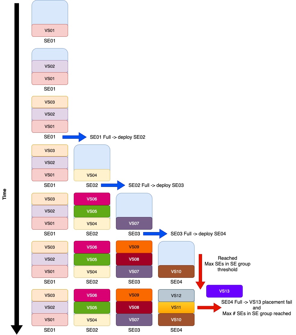
Compact + Buffer $ = $ 0 + Min Scale per VS $ = $ 1
Lets see what happens when we try to place thirteen (13) VSs in our SE group considering our parameters. We will assume that the VSs will be placed in sequence from VS01 to VS13.
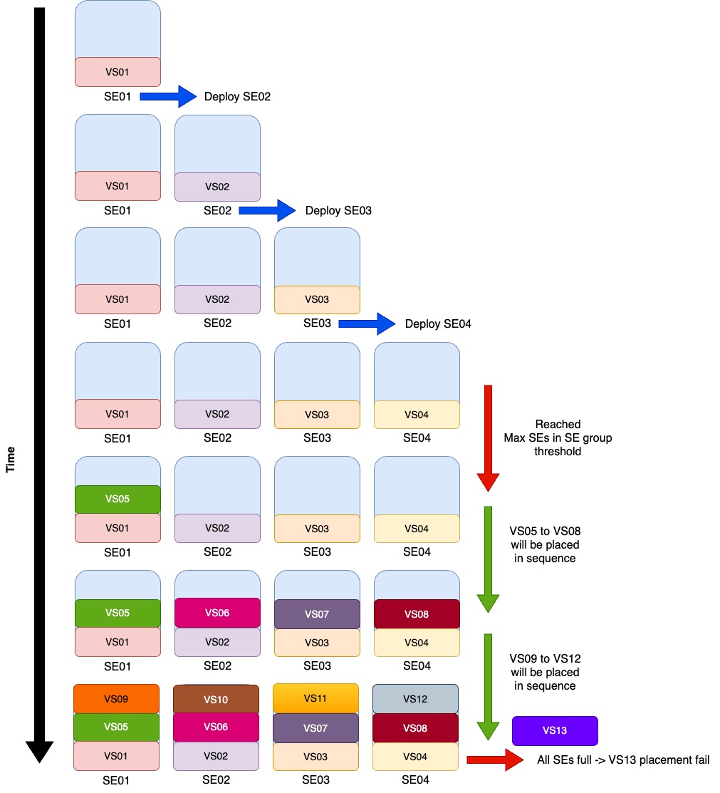
Distributed + Buffer $ = $ 0 + Min Scale per VS $ = $ 1
Same as the previous example, lets try to place our VSs now in a SE group with a Distributed policy instead of Compact.
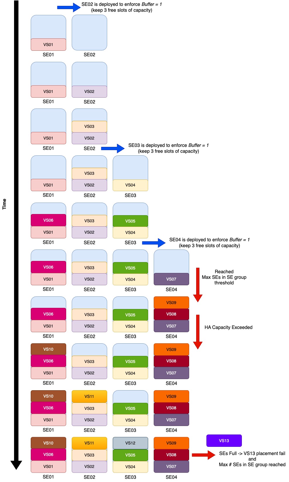
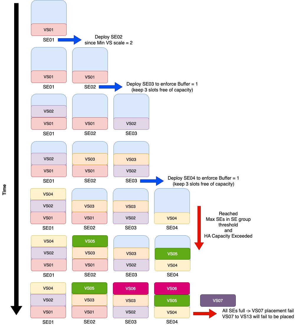
Compact + Buffer $ = $ 1 + Min Scale per VS $ = $ 1
Now lets go back to Compact but increasing the Buffer to one (1).
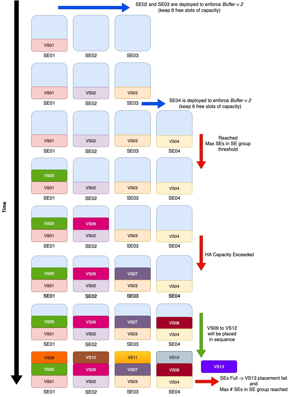
Compact + Buffer $ = $ 2 + Min Scale per VS $ = $ 1
Now lets still go Compact but increasing the Buffer to two (2).
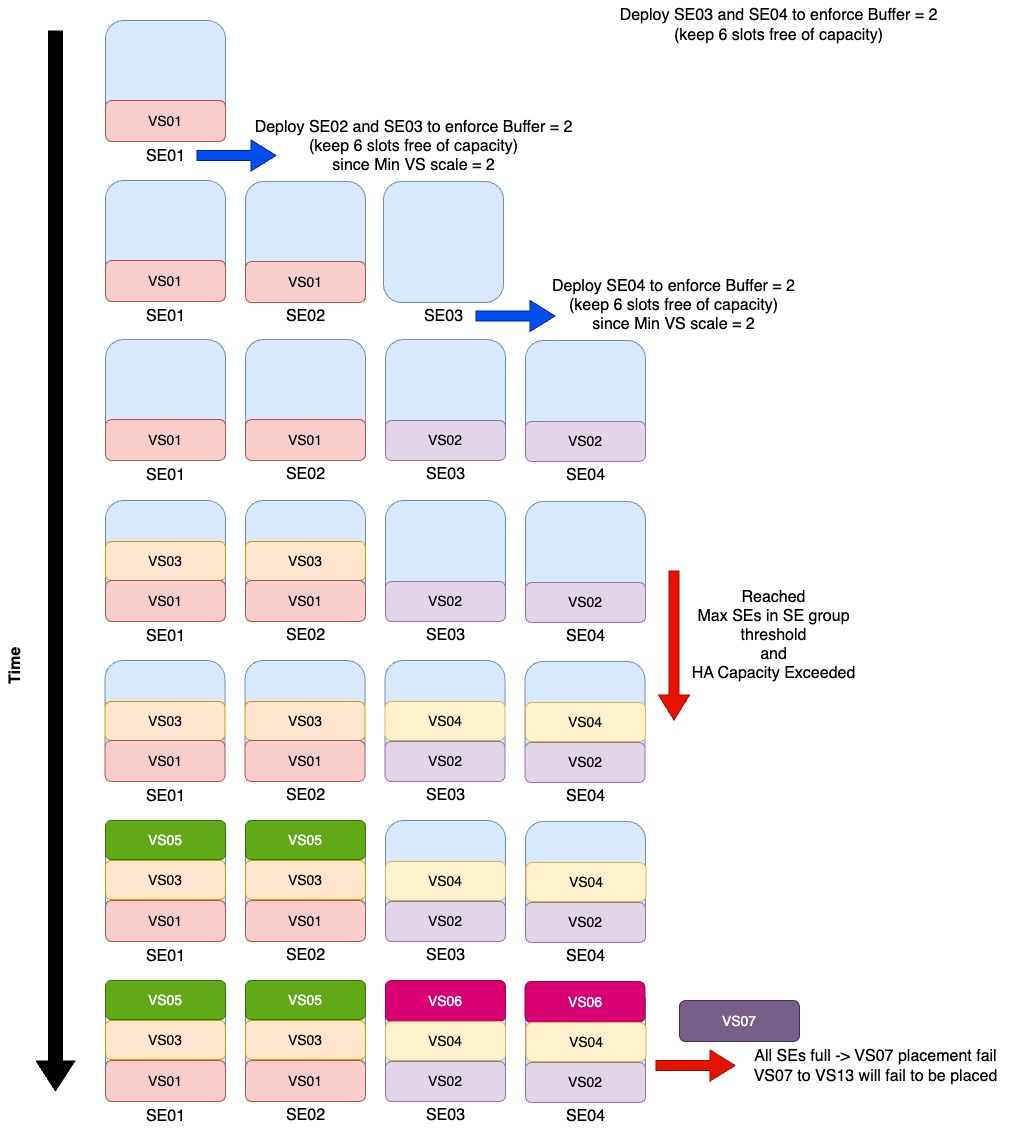
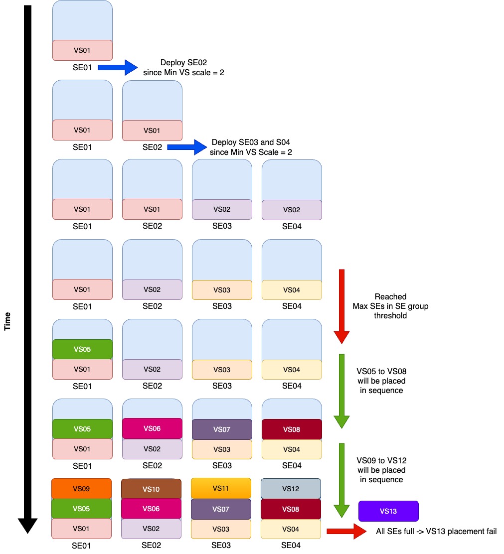
Distributed + Buffer $ = $ 0 + Min Scale per VS $ = $ 2
Still using the same SE Group base parameters, but now lets increase our VS minimum scale to two (2) and use a Distributed policy as per our Active/Active config toggle. From the get go we know that we will not be able to fit the thirteen (13) VSs since for that we will need a capacity of $n = 13 \cdot 2 = 26 $, and we know that our maximum capacity is $ Max cap = 4 \cdot 3 = 12 $.
Distributed + Buffer $ = $ 1 + Min Scale per VS $ = $ 2
Just to exemplify cases where adding a Buffer do not have a benefit, lets use a similar example as the one before Distributed + Buffer $ = $ 0 + Min Scale per VS $ = $ 2 but now with Buffer bumped to one (1).
In this example the result will be pretty much the same since with the Min Scale per VS $ = $ 2 and Distributed policy, the SEs will be deployed as soon as we try to place VS02.
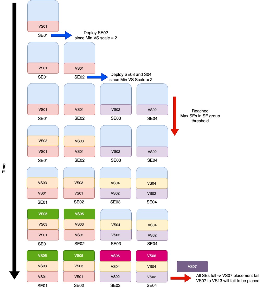
Compact + Buffer $ = $ 1 + Min Scale per VS $ = $ 2
So lets now check what happens if we use a Compact policy instead of Distributed when we set the Min scale per VS $ = $ 2.
Compact + Buffer $ = $ 2 + Min Scale per VS $ = $ 2
And to terminate the use cases lets bump the Buffer to two (2).